Representing 3D objects in 2D drawings
This unit develops students’ ability to represent three dimensional objects using two dimensional representations.
- Use plans from different viewpoints to represent 3D objects.
- Draw isometric drawings of 3D objects.
- Create nets for polyhedra.
- Interpret the above representations to create a model of the 3D object.
In this unit students learn to use two different two-dimensional drawings to represent three-dimensional shapes.
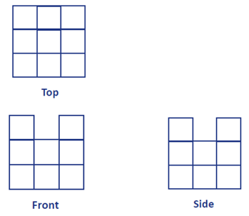
The first type of drawing is the use of plan views. These views are usually from the top, front, and side, as you would see in house plans. Such views are called orthogonal, meaning that the directions of sight are at right angles to each other. The images below show an example of plan views.
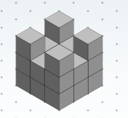
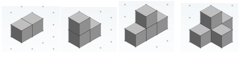
The second type of drawing is perspective, using isometric paper. True perspective shows objects getting smaller as they are further from the point of sight. Iso means “same” and “metric” means measure, so isometric paper shows every cube as the same size. Therefore, an isometric drawing shows a three-dimensional model from a single viewpoint, and distorts the perspective the eye sees. This can be seen in the image below.
In this unit students also work to develop flat patterns (nets) for simple solids, such as pyramids and prisms. A pyramid consists of a base, that names the solid, and triangular faces that converge to a single vertex, the apex. A hexagonal-based pyramid has a hexagonal base and six triangular faces. A prism has two parallel faces, that also name the solid, and parallelogram shaped faces. In right-angled prisms those faces are rectangles. Therefore, prisms have a constant cross-section when ‘sliced’ parallel to the naming faces.
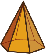
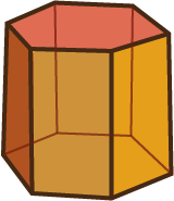
Hexagonal pyramid Hexagonal prism
The flat surfaces of a three-dimensional solid are called faces. All faces must be connected in a net, the flat pattern from which the solid can be built. However, not all arrangements of faces will fold to the target solid. In the net for a hexagonal pyramid there needs to be one hexagon and six triangles, arranged in a way that means when folded there are no overlapping and no missing faces.
The learning opportunities in this unit can be differentiated by providing or removing support to students, and by varying the task requirements. Examples include:
- using physical materials, such as connecting cubes and connecting shapes, so students can build the models they attempt to draw
- beginning with simple cube structures and solids, then building up with competence and confidence
- scaffolding the drawing of a net by rolling the solid through its faces, and sketching around the outside of each face, in turn, to form the net
- using online drawing tools at first, particularly for isometric drawing, to facilitate visualisation, and encourage risk taking
- encouraging collaboration (mahi tahi) among students.
The contexts for this unit can be adapted to suit the interests and cultural backgrounds of your students. Select three-dimensional structures that are meaningful to your students. Mathematical solids are often used in construction, such as the shape of traditional Māori food stores (Pātaka), climbing equipment in playgrounds, and iconic structures around the world, e.g. pyramids of Egypt, high rise buildings.
Consider how you can make links between the learning in this unit, and other recent learning. For example if you have recently visited a local marae, your students might be engaged by the concept of drawing the floor plan of the marae.
Te reo Māori vocabulary terms such as āhua ahu-toru (three-dimensional shape), āhua ahu-rua (two-dimensional shape), āhua (shape), inerite (isometric), tukutuku inerite (isometric grid), raumata (net of a solid figure), tirohanga (perspective), tirohanga pūtahi (one point perspective), and the names of different shapes could be introduced in this unit and used throughout other mathematical learning.
- Multilink cubes or another form of connecting cube
- Polydrons or other form of connecting polygons
- Objects from around the classroom or 3D solids (cube, pyramid, cone, cylinder, sphere, etc.)
- Digital camera
- Cardboard, tape or glue
- Protractors and rulers
- PowerPoint 1
- PowerPoint 2
- PowerPoint 3
- PowerPoint 4
- PowerPoint 5
- Copymaster 1
- Copymaster 2
- Copymaster 3
Session 1
SLO:
- Use plan views to represent three-dimensional models made from cubes
In this context, you might draw on the knowledge of community members (e.g. builders, architexts) and have them show architectural plans to your students.
- Use slides one and two of PowerPoint 1 to introduce the idea of architectural plans.
What are these pictures used for?
Discuss the idea of flat (two-dimensional) drawings used to show the structure of three-dimensional structures.
Sometimes more than one drawing is needed. Why?
Tell the students that today they are becoming architects. - Give a student ten multilink cubes and ask them to create a building for you. The only stipulation is that faces meet exactly.
Show the class the building laying flat on your hand. After a few seconds of viewing time, place the building flat on a desktop. Move to the front of the desk, crouch down and take a digital photograph with the house at lens level.
Draw what you think the photograph looks like. - Let students sketch their idea of the viewpoint. Show the photograph on an interactive whiteboard, television, or using a projector.
How do the cubes show in the photograph? (as squares)
Why do they appear that way? (Only one face of each cube is visible)
What strategies did you use to get the viewpoint correct? (layers or columns, relative position, etc.)
Be aware that many students are likely to have attempted to show depth in their pictures. Point out that the camera can only capture what it sees. - Repeat the exercise for the right-hand and birds-eye views.
Are students understanding that information is lost when a 3D object is represented in 2D diagrams? - Show slide three that depicts a correct layout for plan views. Plan views are often called orthogonal because they are at right angles to faces of the model.
How many cubes make up this building? How do you know? (9 cubes) - Ask students to take nine or ten cubes and make their own building.
Put your building on a desktop.
Draw your building from the front, right side and top.
Provide grid paper (Copymaster 1) to support students with drawing squares. - Roam the room to support students. Taking digital photographs of their models and showing the image is useful for students who find it hard to minimalise the information they show.
- After a suitable time, ask students to bring their plan views to the mat, and to leave the model on a desktop somewhere in the classroom. Gather all the plans, shuffle them, and deal out one per student.
Can you find the model that goes with the plan? - Let students have a suitable time to locate the models. Some plans may have more than one appropriate model.
- Discuss the features they looked for in locating the model.
Which plan was the most useful? (A key point is that one viewpoint, often the top, is a good screening tool for possible models. Other views can be used to confirm the correct model). - Return to Slide Three. Ask the students to use the cubes from their previous model to build a structure that matches the views. Once they believe they have a correct model, students can justify their answer to a partner. Animate Slide Three to reveal the correct answer.
Discuss the use of the top view to organise the information from the other views. - Slides Four and Five have two other plan view puzzles. Animating each slide provides a model answer.
- Students might also work on the Figure It Out activities called Building Boldly and X-ray vision. PDFs are available for the student pages.
Session Two
SLOs:
- Coordinate different views of the same structure to form a model of it.
- Represent cube models with isometric drawing.
Before class gather at least five different shaped objects from around the classroom. The objects might be mathematical models (e.g. cube, pyramid, sphere, etc.) or common objects (book, cone, bottle, box, etc.) or a combination of things. It is better if the objects are different heights.
- Using a large sheet of paper placed on a desktop, draw a grid of squares. 10cm x 10cm squares are a good size. Arrange the objects at different locations on the grid. Take digital photographs with the grid at lens level. Capture views from all four compass points.
- Place the grid on the mat or on a central table.
A spy took these photographs of an enemy city. She took four pictures, one from each of the compass points. After returning to her base she emailed the images.
Show the students all four views of the ‘city’ on an electronic whiteboard or using a data projector.
Your job back at Kiwi Intelligence is to construct a plan map of the city. You know there are these buildings (objects). Look carefully at the photographs to work out where to put each building. - Let students sketch a birds-eye view of the city. They might name the buildings (object) on their plan rather than draw the shapes. After a suitable time, gather the class to decide where to position each object. Look for students to coordinate views to do so.
- It is common for travellers to create optical illusions of places they visit. Images appear impossible, such as someone holding up the leaning tower of Pisa. Slide One of PowerPoint 2 has an illusion like that.
How do these tricks work? (Objects that are further away look smaller, even to a camera. That is called perspective)
How do artists adjust what they draw to allow for perspective? (Show Slide Two) - One way to represent cube models is to use isometric drawing. That method does not have the vanishing points of perspective drawing, but it does partly show that the object is three dimensional. In isometric drawings things that are further away do not get smaller, but all parallel edges remain parallel (Show Slide Three)
- Slide Four shows how to draw a model made with five cubes. Step through the process of drawing slowly with students copying each step on a sheet of isometric paper (Copymaster 2). You might like to go to an online isometric drawing tool (https://www.nctm.org/Classroom-Resources/Illuminations/Interactives/Isometric-Drawing-Tool/) to show how the drawing is built up from the cube that is hidden.
- Ask students to create a model made from interlocking cubes. A maximum of ten cubes is wise. Students sketch their models on isometric paper. The sketches can be given to a partner who makes the model. Sometimes different models can be made for the same drawing.
- Discuss the strategies students used to create correct isometric drawings, such as:
- Begin with the front-most cube.
- Hold the model so the leading edges face up and down.
- Build the drawing across and up first.
- Create an L shape for cubes that come out at right angles.
- Watch for parts of faces that might be visible.
- Imagine a light shining on the model from behind (to shade faces)
- Create some isometric drawings using the online tool. For each, discuss:
- How many cubes are needed to build this model?
- Is that the smallest possible number of cubes?
- What is the largest number of cubes that could be in the model?
- Challenge students with the Figure It Out activity, Cube Creations. In the task students firstly build models from isometric drawings and join the models to create cubes. The second challenge is for them to create a cube puzzle of their own and draw the pieces (models) using isometric paper.
Session Three
SLO:
- Connect plan views and isometric drawings for the same three-dimensional cube model
- Show students Slide One of PowerPoint 3. Provide students with another sheet of isometric dot paper (Copymaster 2).
Draw what this model looks like on isometric dot paper. Before you start, you will need to decide whether to draw the front of the model angled to the left or right. Model looking at the model angled to the left and to the right.
Let students attempt to draw the model. There are two possible perspectives depending on which direction the front is angled. Both drawings are shown on slide two.- Discuss the strategies that were helpful to producing a correct drawing. Ideas might include:
- Identifying which direction is the front.
- Starting with the front most stack of cubes.
- Building the ground layer first before building up.
- Considering the cubes that cannot be seen.
- Erasing unwanted lines.
- Shading faces as you go so the blocks look solid.
- Engage in reciprocal partnerships (tuakana teina) again. Both partners draw a model they create. They choose three plan (front, top, side) or isometric views to draw. The other partner creates a different drawing of the same model, then builds it to check.
- Ask students to work on the Figure It Out activity called A Different View. In this activity students match isometric views, with directional arrows, to the corresponding plan views from those perspectives. They also draw 2D representations of everyday objects such as cups and paper clip holders. A PDF of the student page and answers are provided. An extension activity can also be found in Missing Anything, a Level 4+ Figure It Out page.
Session Four
SLO:
- Create nets for simple solids (prisms and pyramids).
- Begin this session by showing your students some graphics of simple solids. Slides One to Three of PowerPoint 4 show three types of prism, triangular, hexagonal and rectangular (cuboid). Show each solid in turn, and ask:
Where are you likely to see a shape like this?
What is the shape in this picture called?
What are the shapes of its faces?
How many vertices (corners) and edges does it have? - Discuss: What do all three solids have in common?
The common properties that define a prism are, a solid that has two identical parallel faces and all other faces are parallelograms.
Slide Four shows a loaf of bread being sliced.
How are a loaf of bread and a prism the same? - Prisms are sometimes defined as solids with constant cross section. Slices of bread are a similar shape. It is the cross-section that determines the name of a prism. Slide Five shows a pentagonal prism as the cross section is a five-sided polygon.
- Show Slide Six.
Here is a rectangular prism shaped box that holds soap powder.
Imagine that I open out the packet to form the flat pattern that makes it.
Sketch what you think the net will look like. - You may give students copies of Copymaster 1 to make measurement of length, and creating right angles, easier. Encourage students to create a net (flat pattern) that folds exactly to form the packet. Roam the room and look for:
- Do students attend to the shape of faces in constructing the net?
- Do they visualise the effect of folding up faces?
- Do they consider which sides of the net will need to be the same length for edges to form correctly?
- Do they consider tabs needed for gluing the net together? (Usually every second side of the net.)
- Provide Slides Seven and Eight for students to create their own nets. The triangular and hexagonal prisms are more challenging than the cuboid, particularly getting the angles and side lengths correct. You may need to support some students to create 60⁰ internal angles for equilateral triangles and 120⁰ angles for regular hexagons. Use protractors to get accurate measures.
- Show Slide Nine that shows the three nets.
What is the same about all three nets? (Rectangular faces in a line)
What is different about the three nets? (Parallel faces that create the cross section)
How can you tell how many rectangular faces the prism needs? (The number of rectangular faces equals the number of sides on one of the parallel faces)
Visualise the net for the pentagonal prism. What does that net look like? (Five rectangles in a line, with two pentagonal faces). - Slide Ten gives images of three pyramids; tetrahedron (triangular based), square based, and hexagonal based pyramid.
What are these three-dimensional shapes called?
In what way are the solids related?
Look for students to discuss the properties of a pyramid; a base of a given shape, triangular faces that meet at an apex. - Challenge your students to create nets for the three pyramids. Blank A3 paper, a protractor and ruler are useful. Roam the room. Look for students to:
- Construct a base that is a regular polygon (same side lengths and angles)
- Arrange the triangular faces so they emanate from each side of the base shape
- Construct isosceles triangles with two equal sides for the lateral faces.
- Constructing a pentagonal, octagonal or dodecagonal based pyramid is an excellent challenge for students who are competent.
Let students investigate the problem in pairs and record their ideas. - Use the models of prisms and pyramids to look at the number of faces, edges, and vertices in each solid. Discuss systematic ways to count. For example, to count the edges of a prism, count around each parallel face and add the lateral edges.
- Create tables for the solids you have models for.
Look at the table for prisms together (see below):
Number of faces
Number of edges
Number of vertices
Triangular Prism
5
9
6
Rectangular Prism
6
12
8
Pentagonal Prism
7
15
10
Hexagonal Prism
8
18
12
- Ask: If you know the number of sides of the cross section, can you predict the number of faces, the number of edges, and the number of vertices?
Students might notice that:- The number of faces is two more than the number of sides in the cross section. Why?
- The number of edges is three times the number of sides in the cross section. Why?
- The number of vertices is two times the number of sides in the cross section. Why?
Look at the table for pyramids together (see below):
Number of faces
Number of edges
Number of vertices
Triangular Pyramid
4
6
4
Square based Pyramid
6
8
5
Hexagonal Pyramid
8
12
7
- Ask: If you know the number of sides of the base shape, can you predict the number of faces, the number of edges, and the number of vertices?
Students might notice that:- The number of faces is one more than the number of sides of the base shape. Why?
- The number of edges is double the number of sides in the base shape. Why?
- The number of vertices is one more than the number of sides of the base shape. Why?
Session Five
SLOs:
- Establish whether, or not, a given net for a simple solid is viable.
- Visualise which sides and corners of a given net will meet when the net is folded.
- Begin with Slide One of PowerPoint 5 that shows a viable, though unconventional, net for a triangular prism.
Will this net fold to form a solid?
Which solid will it create?
How do you know? (Consider the number and shapes of faces, the result of folding) - Mouse click and a single corner of the net will be highlighted.
Imagine this net is folded. What other corners of the net will meet? - Mouse clicks reveal the other corners that meet.
- Another mouse click shows a side of the net.
Which other side meets this one when the net is folded?
How do you know? - Mouse click to see the other side that connects.
- Discuss how many corners meet to form a vertex (three) and how many sides form an edge (two).
- Ask similar questions for Slides Two and Three that show other nets.
- Provide students with Copymaster 3 that contains a set of similar folding puzzles for different solids. Students might work in collaborative, small groups and justify their solutions to each other. Tell them that their first task is to decide whether, or not, the net folds to make a solid.
- Gather the class after an appropriate time and discuss the strategies students used. Ideas that might emerge are:
- Imagine the net is folded and tracking the destination of corners and sides as they form vertices and edges of the target solid.
- Consider the properties of the target solid, e.g. parallel faces of a prism, corners of a pyramid converging apex.
- Eliminate obvious corners and sides first.
- Recognise when the positioning of shapes in a net, results in overlaps, or omissions of faces, in the target solid.
- Challenge students to create similar puzzles for their classmates. The net may be possible or impossible and they should choose a corner and a side that challenges the solver.
- Extra activities related to nets can be found using these Figure It Out resources: