Circuit Problems
The purpose of this unit is to engage students in applying their understanding of algebra to solve problems within the science - physical world context of electrical circuits. Subsequently, students develop their skills and knowledge on the following mathematics learning progression: Using Symbols and Expressions to Think Mathematically
- use algebra to generalise the results of a practical investigation.
- apply knowledge of circuits, power, voltage, currents, and resistance to problem solving.
- use graphical techniques to identify and describe a linear relationship found in a practical investigation.
This unit integrates mathematical skills and knowledge with the science learning area and provides opportunities for students to explore the relationships between currents in and voltages across different parts of a circuit.
To ensure engagement and participation in this unit, you should consider your students' prior knowledge of circuits, currents, voltage, electricity, as well as their understanding of graphical and algebraic techniques and linear relationships.
This unit includes practical activities that can be carried out using standard science lab equipment, or materials that can be purchased at electronics stores (wires, multi-meters, batteries and component resistors). You should ensure that any current reading is carried out in series, and that any voltage reading in parallel, regardless of whether multi-meters or ammeters and voltmeters are used. Ammeters (and multi-meters set to a current reading) are easily damaged if placed incorrectly. Check that ammeters and voltmeters are connected correctly with a very short momentary connection (the touch test) to see that the needle moves clockwise and not past the end of the scale.
This cross-curricular, context-based unit aims to deliver mathematics learning, whilst encouraging differentiated, student-centred learning.
The learning opportunities in this unit can be further differentiated by providing or removing support to students, and by varying the task requirements. Ways to differentiate include:
- roaming and supporting students in a variety of groupings to ensure they understand the task at hand, the skills needed to succeed, and can apply these skills in a suitable process
- varying the amount of structured scaffolding and guided teaching you provide to students when investigating new tasks
- providing opportunities for students to create their own problems related to the learning scaffolded in the unit
- providing extended opportunities for students to revise and apply learning from throughout the unit
- modelling the application of ideas at every stage of the unit
- strategically organising students into pairs and small groups in order to encourage peer learning, scaffolding, and extension
- allowing the use of calculators to reduce the cognitive load required in each task
- working alongside individual students (or groups of students) who require further support with specific areas of knowledge or activities (e.g. constructing circuits and graphs).
This unit is focussed on applying algebraic and graphic knowledge to the physical world context of electrical circuits. As such, it is not set in a real world context. You may wish to explore real world applications of this content in following, or additional sessions. For example, a community expert might be able to come to your class to discuss their use of circuits, and their knowledge of voltage, currents etc., in an occupation or leisure activity.
Structure
The first session is an introductory activity that is aimed to spark the imagination of students, to introduce the need for a particular idea or technique in mathematics that would enable them to explore deeper into that context. It is expected that rich discussion may be had around the context and around the nature of the mathematics involved.
Following the introductory session, each subsequent session in the unit is composed of four sections: Introducing Ideas, Building Ideas, Reinforcing Ideas, and Extending Ideas.
Introducing Ideas: It is recommended that you allow approximately 10 minutes for students to work on these problems, either as a whole class, in groups, pairs, or as individuals. Following this, gather the students together to review the problem and to discuss ideas, issues and mathematical techniques that they noticed during the process. It may be helpful to summarise key outcomes of the discussion at this point.
Building Ideas, Reinforcing Ideas, and Extending Ideas: Exploration of these stages can be differentiated on the basis of individual learning needs, as demonstrated in the previous stage of each session. Some students may have managed the focus activity easily and be ready to attempt the reinforcing ideas or even the extending ideas activity straight away. These could be attempted individually or in groups or pairs, depending on students’ readiness for the activity concerned. The students remaining with the teacher could begin to work through the building ideas activity together, peeling off to complete this activity and/or to attempt the reinforcing ideas activity when they feel they have ‘got it’.
It is expected that once all the students have peeled off into independent or group work of the appropriate selection of building, reinforcing and extending activities, the teacher is freed up to check back with the ‘early peelers’ and to circulate as needed.
Importantly, students should have multiple opportunities to, throughout and at the conclusion of each session, compare, check, and discuss their ideas with peers and the teacher, and to reflect upon their ideas and developed understandings. These reflections can be demonstrated using a variety of means (e.g. written, digital note, survey, sticky notes, diagrams, marked work, videoed demonstration) and can be used to inform your planning for subsequent sessions.
The relevance of this learning can also be enhanced with the inclusion of key vocabulary from your students' home languages. For example, te reo Māori kupu such as kauwhata (graph), tūtohi (table/chart of data), and pānga rārangi (linear relationship) might be introduced in this unit and then used throughout other mathematical learning.
- Images of the circuits used throughout the unit
- Standard science lab equipment or materials from electronics stores (wires, multi-meters, batteries and component resistors)
Introducing Ideas
Introduce the following context to students: The standard unit of power, the rate at which energy is transformed, is the watt. One watt is equivalent to one joule per second. Energy companies bill electrical usage in units of kilowatt hours (kWh). The average annual household electricity usage is 7600 kWh.
How many joules of electrical energy does the average daily household use?
Observe how your students use the given units of measurement to understand the mathematical relationship between quantities. Use these observations to locate your students on the following learning progression: Using Symbols and Expressions to Think Mathematically.
Discuss, drawing attention to the following points:
Household usage accounts for 13% of the total electricity usage in the New Zealand.
What is the total annual electricity usage in the New Zealand?
Why might energy companies measure energy in kWh rather than J?
Why might energy companies measure power in kW or GW rather than W or Js-1?
Session One
This session focuses on problem solving.
Introducing Ideas
Introduce the following problem to students: When the Smith family was at work and school for six and a half hours, they left enough lights and appliances running to draw a current of 30 A. An ampere, A, measures the amount of charge running through the meter every second. The power supplied to the house is at 230 V. A volt, V, is a measure of the amount of electrical energy transformed per unit charge.
How much electrical energy did the Smith family’s house use in their absence that day?
Discuss, drawing attention to the following points:
- Can we use the definitions of current and voltage to find a way of measuring the current and voltage to find the power used?
- How can we work out the electrical energy used given electrical power used and the time it is used over?
- Can we use the definitions of current and voltage to find a way of measuring the energy used in a given time?
Building Ideas
Explain: Power, measured in W, is calculated from the rule P = VI:
Provide time for students to work through the following tasks, Remind and support students to use appropriate units in their calculations.
- What do the symbols, P, V and I stand for?
- Use this rule to find the power output of a heater that operates on 230 V and draws a current of 7.8 A.
- Use this rule to find the voltage of a 2000W heater that draws a current of 10 A.
Reinforcing Ideas
Introduce the following context to students: Power, measured in W, is the rate at which energy is used. Power is the product of the voltage across and current through an electric supply electric circuit or any appliance using electricity.
Provide time for students to work through the following tasks. Remind and support students to use appropriate units in their calculations.
- Write this rule as an algebraic equation using P for power, V for voltage and I for current.
- Use the rule to find the power output of a torch that uses a single AA ‘battery’ of 1.5 V and draws a current of 0.2 A.
- Use the rule to find the voltage of a 2000W heater that draws a current of 8.7 A.
- What is the total electrical energy transformed by the heater if it is switched on for 2 hours?
Extending Ideas
Provide time for students to work through the following task. Remind and support students to use appropriate units in their calculations.
Find the difference in energy usage of an oil heater that runs for 4 hours, drawing a current of 8.5 A on mains electricity over a 425 W panel heater that is left running for 12 hours.
Session Two
This session focuses on using algebra to generalise the results of a practical investigation.
Introducing Ideas
Introduce the following context to students: Electrical current, in amperes (A) is defined as the rate of flow of charge. It is measured with an ammeter placed in series in a circuit. Look at the circuit below:
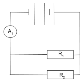
Provide time for students to work through the following tasks:
- Identify the ammeter in this circuit.
- If the ammeter was used to measure the current in the resistor R1, where would it be placed?
- If the ammeter was used to measure the current in the resistor R2, where would it be placed?
Discuss, drawing attention to the following points:
- Why are ammeters placed in series in the circuit?
- What might we expect the relationship between the readings on the ammeter in these three positions to be? (I.e. the same, different, related in some way – and if so why?)
Building Ideas
Provide time for students to work through the following tasks:
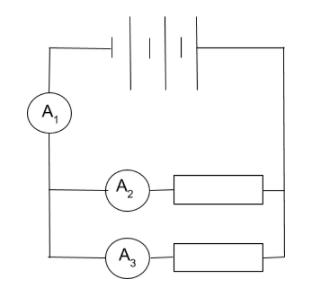
- Build the circuit above, measuring the current supplied (A1) by three 1.5 cells connected in series, to two 50 Ω resistors connected in parallel.
- Measure the current through each of the resistors (A2 and A3).
- Describe the relationship between A2 and A3.
Reinforcing Ideas

Introduce the following context to students: Current is the rate of flow of charge. The two resistors in the circuit above are the same size.
Provide time for students to work through the following tasks:
- If the current in A1 is 5 A, what will the readings on each of A2 and A3 be?
- If the current in A1 is 0.2 A, what will the readings on each of A2 and A3 be?
- If the reading on A2 is 2 A, what will the readings on each of A1 and A3 be?
- If the reading on A2 is 0.15 A, what will the readings on each of A1 and A3 be?

Provide time for students to build the above, using three 1.5 cells connected in series, to two resistors chosen from a selection of 50 Ω and 100 Ω resistors and connected in parallel so that A2 = 2A3. They should then be supported to do the following:
- Copy and label the circuit diagram with the size of the resistors used and the currents through each.
- Predict the total current supplied (A1 ) by three 1.5 cells.
- Measure the total current supplied (A1 ) by three 1.5 cells.
- Explain the similarities/differences between the currents you found for activities 3 and 4.
Session Three
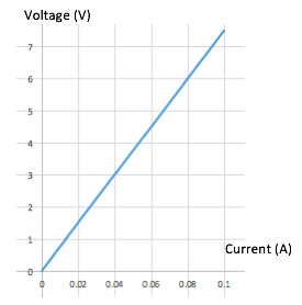
- Introduce the following context to students: The current in a circuit is controlled by the size of the load, the resistance of the components in the circuit. Resistance, R (in Ω) is the gradient of the linear relationship; voltage against current.
- Find the resistance of the circuit described by the graph below.
- Discuss, drawing attention to the following points:
- How can we ensure accuracy when finding the gradient of this graph?
- Give the unit Ω in terms of volts and amperes.
- To gather the data for this graph, a variable power supply was used. Give suitable instructions for carrying out this experiment.
- Set up the following circuit.
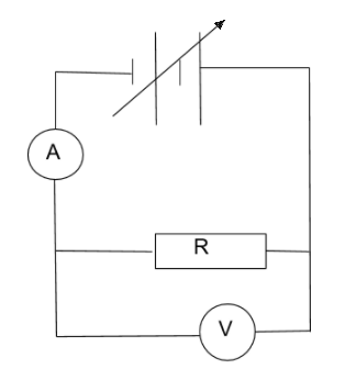
- Have students do the following:
- vary the voltage and complete the table below.
| V (V)0.5 | 1.0 | 1.5 | 2.0 | 2.5 |
| I (A) |
- construct the graph of voltage against current.
- describe the relationship between voltage and current.
Reinforcing Ideas
- Set up the following circuit and measure the data necessary to graph voltage against current.
- Vary the voltage to obtain at least four data points.
Provide time for students to work through the following tasks:
- Find the gradient of the line of best fit from your graph of voltage against current.
- What is resistance of R in your circuit? Give your answer with the appropriate units.
Extending Ideas
- Have students do the following:
- investigate the circuit shown in the diagram below to find the relationship of voltage in terms of current.
- write the general rule for this relationship using the symbols V, I and R.
- find the power output of the resistor in this circuit.
Session Four
Introduce the following context to students: The relationship between current, voltage and resistance of an electrical component, or of a circuit, is known as Ohm’s Law. It is:
V = I RTogether, use this rule to find the current drawn by a 50 Ω kettle connected to mains electricity (230 V).
Discuss, drawing attention to the following points:
- What is the power output of this kettle?
- Explain the energy transformation(s) when the kettle is switched on.
Building Ideas
Provide time for students to use Ohm’s Law, V = IR, to solve the following problems. Remind and support students to use appropriate units in their calculations.
- Find the voltage across a 60 Ω resistor which is drawing a 2.5 A current.
- Find the voltage across a 60 Ω resistor which is drawing a 7.5 A current.
- Find the voltage across a 120 Ω resistor which is drawing a 2.5 A current.
- Find the voltage across a 150 Ω resistor which is drawing a 2.5 A current.
Reinforcing Ideas
- Provide time for students to use Ohm’s Law, V = IR, to solve the following problems. Remind and support students to use appropriate units in their calculations.
- Find the voltage across a 500 Ω resistor which is drawing a 7.5 A current.
- Find the current drawn by a 500 Ω resistor connected to a 12 V supply.
- Find the current drawn by a 500 Ω resistor connected to a 12 V supply.
- What is the resistance of a component connected to a 9.0 V supply that draws a 3 A current?
Extending Ideas
- Provide time for students to use Ohm’s Law, V = IR, to solve the following problems. Remind and support students to use appropriate units in their calculations.
- Find the voltage across a 500 Ω resistor which is drawing a 7.5 mA current.
- Find the current drawn by a 500 Ω resistor connected to a 3000 mV supply.
- Find the current drawn by a 0.75 kΩ resistor connected to a 12 V supply.
- What is the resistance of a component connected to a 9.0 V supply that draws a 300 mA current?
Session Five
This session focuses on using algebraic techniques to solve problems involving power, voltage, current, and resistance.
Introducing Ideas
- Together, use the rules V = IR and P = VI, to find the relationship between power, voltage, and resistance, and between power, current, and resistance.
- Discuss, drawing attention to the following points:
- Describe how increasing the load (resistance) of a mains electrical circuit would affect the current drawn.
- Describe how increasing the load (resistance) of a mains electrical circuit would affect the power output.
Building Ideas
Introduce the following context to students: A heater with resistance of 1500 Ω is connected to a 230 V supply.
Provide time for students to work through the following tasks. Remind and support students to use appropriate units in their calculations.
- Use Ohm’s law, V = IR, to find the current drawn by the heater.
- Find the power output of the heater.
- Find the energy output of the heater over one hour.
Reinforcing Ideas
- Provide time for students to work through the following tasks. Remind and support students to use appropriate units in their calculations.
- Find the current drawn by a 1000 Ω resistor connected to a 230 V supply.
- Find the power output of a 1000 Ω resistor connected to a 230 V supply.
- Find the current drawn by a 2000 W heater connected to a 230 V supply.
- Find the resistance of a 2000 W heater connected to a 230 V supply.
Extending Ideas
- Provide time for students to use the relationships they have derived to:
- Find the power output of a 2.5 kΩ resistor connected to a 230 V supply.
- Find the resistance of an 1800 W heater connected to a 230 V supply.
- If an 1800 Ω heater is replaced by a 600 Ω heat pump, find the relative energy savings (in kWh) over one hour of use connected to mains (230 V).
Remind and support students to use appropriate units in their calculations.
Dear parents and whānau,
In class, we have been applying our understanding of algebra to solve problems within the science - physical world context of electrical circuits. Ask your child to share their learning with you.